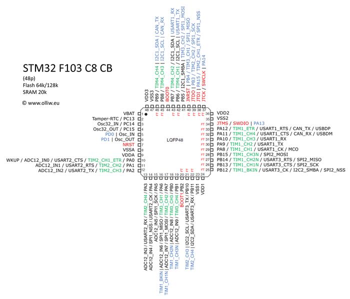
STM32: Difference between revisions
imported>Rmarko another link |
imported>Rmarko locking |
||
| Line 11: | Line 11: | ||
in Main flash memory and System memory boot modes address is aliased to 0x0 | in Main flash memory and System memory boot modes address is aliased to 0x0 | ||
}} | }} | ||
=== STM32F103C86T dev board boot pins === | === STM32F103C86T dev board boot pins === | ||
| Line 133: | Line 135: | ||
* use make V=1 when make fails | * use make V=1 when make fails | ||
====== Locked device ====== | |||
If you can't flash and 'make V=1 flash' reports something similar | |||
{{cmd|code= | |||
Info : Device Security Bit Set | |||
stm32x unlocked | |||
}} | |||
You need to unlock your device first (with JTAG): | |||
* openocd -f jlink_swd_f103.cfg | |||
* telnet 127.0.0.1 4444 | |||
* in telnet issue: stm32f1x unlock 0 | |||
= Calculating Timer Frequency = | = Calculating Timer Frequency = | ||
Revision as of 19:46, 9 November 2016
STM32 programming
Boot mode configuration
<syntaxhighlight lang="bash">BOOT0 BOOT1 Boot mode Address
 x     0   Main Flash memory                      0x8000000
 0     1   System memory (built-in bootloader)    0x1FFFB000
 1     1   Embedded SRAM                          0x20000000
in Main flash memory and System memory boot modes address is aliased to 0x0</syntaxhighlight>
STM32F103C86T dev board boot pins
- https://www.aliexpress.com/item/Free-Shipping-STM32F103C8T6-ARM-STM32-Minimum-System-Development-Board-Module-Forarduino/32525208361.html
- http://www.ebay.com/itm/STM32F103C8T6-ARM-STM32-Minimum-System-Development-Board-Module-For-Arduino-DHUS-/321569700934?pt=LH_DefaultDomain_0&hash=item4adf0c3c46
Legend
<syntaxhighlight lang=" Reset button --- ">o o o BOOT1 o o o BOOT0 ---</syntaxhighlight>
Boot to bootloader (built-in bootloader)
- Allows flashing over USART
<syntaxhighlight lang=" --- ">o [=] [=] o ---</syntaxhighlight>
Boot to main flash (user code)
<syntaxhighlight lang=" --- ">[=] o o o o ---</syntaxhighlight>
Flashing
- Flashing is done via USART1 (A9 TX A10 RX)
Converting Elf to Bin
Required if you only have elf files produced by your toolchain - stm32flash accepts only *.bin files.
<syntaxhighlight lang="bash"> arm-none-eabi-objcopy -O binary miniblink.elf miniblink.bin </syntaxhighlight>
Using stm32flash
Test connection with
<syntaxhighlight lang="bash"> stm32flash /dev/ttyUSB0 </syntaxhighlight>
Flash and run from 0x0
<syntaxhighlight lang="bash"> stm32flash /dev/ttyUSB0 -w miniblink.bin -g 0x0 </syntaxhighlight>
Pinout
Libraries
libopencm3
Minimalistic firmware library/framework.
Bootstrapping on Fedora
Library
- dnf install arm-none-eabi*
- mkdir embedded
- git clone https://github.com/libopencm3/libopencm3
- cd libopencm3
- # Edit TARGETS in Makefile and keep only targets that you need (or just stm32/f1 for example).
- make -j8
- cd ..
DFU bootloader
This is a bootloader for Device Firmware Update via USB (stm32/f1).
- git clone https://git.48.io/libopencm3_dfu
- cd libopencm3_dfu
- # connect JTAG
- make flash
- # or flash via USART & stm32flash, see flashing section above
- make stm32flash
Sample application
For use with DFU bootloader (stm32/f1).
- git clone https://git.48.io/libopencm3_template
- cd libopencm3_template
- # flash via dfu
- make dfu
- # or with JTAG
- make flash
Library examples
- git clone https://github.com/libopencm3/libopencm3-examples
- # Either fetch git submodule pointing to libopencm3 and repeat steps in Library section
- # or symlink libopecm3 dir to previously built libopencm3
- cd libopencm3-examples
- rmdir libopencm3
- ln -s <PATH_TO-->/libopencm3 .
- # try building miniblink example
- cd examples/stm32/f1/stm32-h103/miniblink
- make
Troubleshooting
- use make V=1 when make fails
Locked device
If you can't flash and 'make V=1 flash' reports something similar
<syntaxhighlight lang="bash">Info : Device Security Bit Set stm32x unlocked</syntaxhighlight>
You need to unlock your device first (with JTAG):
- openocd -f jlink_swd_f103.cfg
- telnet 127.0.0.1 4444
- in telnet issue: stm32f1x unlock 0
Calculating Timer Frequency
MUCH WIP
period_target_ms = p1 period_hz = p2
1000ms / p1 = p2
E.g. for 20ms (servo) period
1000ms / 20 ms = 50 hz
cpu_freq = 72Mhz prescale = 72
72MHz / 72 = 1Mhz
This increases out count register CNT by 1 000 000 each second. To calculate what is the correct value for the ARR register (which defines the period), we divide the result of the prescaled frequency by the intended frequency for our period:
1 000 000 Hz / 50 Hz = 20 000
Now every time the CNT register is increased by one, this is the equivalent to 1us. The duty cycle now could by set easily. E.g. for a 1.5ms duty cycle we set the CCRx register to 1500.
Stepper
driver_max_duty = 250khz
